Telephone
13969090828

The Performance Level (PL) of a safety-related control system shall be established before system design and component selection. Based on the fundamental requirements of EN ISO 13849-1:2023, this article sets out the basis for determining the required Performance Level (PLr), the principles for judging the risk-map parameters S, F and P, and the key principle that the risk-reduction effect of a safety function itself must not be used to back-calculate the PLr. Drawing on the physical protective-barrier product portfolio of Shandong Jingmei Security Equipment Co., Ltd., it then explains how risk-assessment conclusions can be translated into sound engineering protection solutions across industrial scenarios.
In industrial safety-protection practice, two common approaches are both directionally flawed. The first is to fill in a project's PLr by reference to the highest Performance Level of the safety relay that has been purchased. The second is to directly carry over the grade experience from previous equipment to a new project. The common problem is that PLr determination lags behind, or is even made subordinate to, hardware selection, rather than guiding design from the outset.
According to Clause 5.3 of EN ISO 13849-1:2023, the required Performance Level PLr shall be determined and recorded separately for each identified safety function, rather than assigning a single safety grade to an entire machine or production line. On the same machine, guard-interlocking stop, physical isolation of hazard zones, personnel-approach detection and reduced speed, and prevention of unexpected start-up each address different hazardous sources, become effective under different operating conditions, and carry different risk-reduction tasks; their corresponding PLr values may therefore differ significantly.
Before entering the circuit-design and component-selection stage, three preparatory tasks shall first be completed:
A complete safety-function definition shall, at a minimum, cover: the hazardous movement or hazardous source it protects against (e.g. an industrial robot's operating envelope, a laser beam path, a die-casting closing area, live parts in an energy-storage cabinet); the trigger condition (e.g. opening of a guard door, detection of personnel entering a monitored area, activation of maintenance mode); the safe state entered (e.g. stop, de-energization, speed restriction, torque restriction); the applicable operating modes and boundary conditions; and the maximum permissible stop time or response time.
Where these elements differ, even if the same model of door switch or light curtain is used, the same PLr conclusion must not be carried over directly. If the safety function is not clearly defined, the subsequent PLr determination has no clear object.
EN ISO 13849-1 is a B-type generic safety standard that provides methods for the design and assessment of safety-related control systems, but does not directly specify PLr values for particular types of machinery. In a specific project, one should first check whether an applicable C-type standard exists, and confirm that its machinery, hazardous sources and coverage match the project; whether it already specifies PLr, architecture Category or other technical requirements; and whether the on-site application falls within its scope.
The C-type standards directly relevant to the industries served by Jingmei include, but are not limited to:
| Application field | Corresponding standards | Key constraints |
|---|---|---|
| Industrial robots and robotic workcells | ISO 10218-1/-2 | Clearance distances for protective fencing, guard-door interlocking, speed and torque limitation in teaching mode |
| Laser processing equipment | IEC 60825 series | Beam enclosure, observation-window materials, interlocked-door requirements |
| Energy-storage stations and storage cabinets | National and industry codes for energy storage | Fire isolation, electrical safety, maintenance-access protection |
| Die casting, forging, machine-tool loading/unloading | Corresponding host-machine C-type standards | Anti-crush, anti-entanglement, anti-ejected-parts protection |
Where a C-type standard already provides for the relevant safety function, the C-type standard shall be applied, and the grade shall not be lowered by instead using the generic risk-map method to arrive at a lower level. Only where a C-type standard does not cover the matter, or where the application falls outside its scope, may the PLr be further determined using the risk-map method in Annex A. Annex A is an informative annex; the risk map is a guidance method, not the only permissible assessment path.
Where the risk-map method is required, three parameters are involved: severity of injury S, frequency and duration of exposure F, and possibility of avoidance P. Each shall be judged on the basis of on-site facts, not on estimated experience or on the absence of past accidents.
S1 denotes minor, usually reversible injury; S2 denotes serious, usually irreversible injury, or death. S is judged by the severity of the possible consequence, not by the accident record. The fact that a machine has run for years without an accident cannot be used to downgrade S2 to S1. Crushing within a robot's operating envelope, direct laser exposure, and splashing of molten metal in a die-casting area should normally be judged as S2.
F1 denotes infrequent and/or short-duration exposure; F2 denotes frequent and/or long-duration exposure. Annex A.3.2 gives a reference condition for F1: cumulative exposure time does not exceed 1/20 of total operating time, and exposure frequency is no greater than once every 15 minutes. This condition should be judged as a whole; F1 should not be selected solely because entries are few.
A machine's daily operating duration cannot be equated with personnel exposure duration. Conversely, entering once a day but remaining for a long time (e.g. maintenance, slag removal, die change) should not simply be judged F1. When multiple operators take turns approaching the same hazard, the exposure-frequency level must not be lowered by apportioning exposures among individuals.
P1 denotes that, under specified conditions, harm can be avoided or limited; P2 denotes that avoidance is almost impossible. P shall take into account the speed at which the hazard arises, personnel's ability to perceive it, available evacuation space and time, task complexity, and operator skill. Training, warning signs and cautious-operation instructions should not, on their own, justify P1. P describes the possibility of avoiding harm when a hazard occurs — it is not the same as machine failure probability or accident probability, and the three must not be confused.
Assuming each parameter has a sound basis and the low-probability correction of Annex A.2 is not introduced, Figure A.1 gives the following branch relationships:
| Parameter combination | Resulting PLr |
|---|---|
| S2 + F1 + P1 | c |
| S2 + F1 + P2 | d |
| S2 + F2 + P1 | d |
| S2 + F2 + P2 | e |
Even where severity is S2 throughout, any change in exposure grade or avoidance possibility may raise the PLr by one level. Disagreement over PL c versus PL d is, in essence, disagreement over on-site facts; it should be resolved by clarifying those facts, not by negotiating a convenient target grade. The parameters are the conclusion of risk determination, not a means of adjusting the grade — it is forbidden to select S/F/P values in reverse order to obtain a desired grade.
When determining the PLr of a given safety function, the assessment starting point is the risk situation before that function comes into play. A common circular argument is: “Once the guard door is opened, the machine stops, so personnel cannot contact the danger” — and on that basis the PLr of the interlock is lowered. In fact, reliable stopping when the door opens is precisely the objective the interlock is supposed to achieve; assuming it will be achieved before the PLr is determined, and using that assumption to depress the grade, is self-validation.
This does not mean ignoring other protective measures. Under Annex A.2, two additional risk-reduction contributions may be counted: first, technical measures independent of the safety control system, such as fixed guarding and physical barriers; and second, the risk reduction provided by other safety functions whose PLr is already determined. When counting these, confirm whether the measures act on the same hazard, are independent of the function being assessed, and are not being double-counted.
Only after the PLr is determined may one design the safety-related control system and select components, assessing the actually achievable PL via architecture Category, MTTFD, average diagnostic coverage DCavg and common-cause failure (CCF), then comparing it with the PLr. Complex projects are usually modelled with tools such as SISTEMA for the PFH calculation, but the software result is only an aid; component selection, circuit design, fault analysis, safety principles, safety software and on-site functional verification must still be confirmed item by item.
Within this chain, Jingmei's core role lies in physical protective barriers and safety-function interfaces — extending forward to safety-function definition and risk-assessment consulting, and backward to supporting system integrators in functional verification.
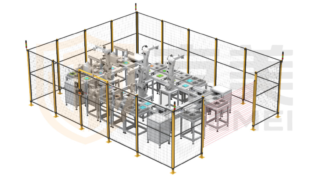
A physical barrier still blocks personnel from the hazard even when the electrical safety circuit fails, the light curtain is bypassed, or the control system malfunctions. Jingmei offers three series of protective fencing:
Access openings are the most risk-intensive points in a barrier system. Sliding doors use a modular design, heavy-duty connections and a fully powder-coated welded structure (opening height 2000 or 2200 mm). Electric sliding doors are available left-opening, right-opening or double-leaf, with single-leaf widths 1500/2000 mm, double-leaf widths 3000/4000 mm, heights 1200/2000/2200 mm, and support for face recognition, fingerprint, card swipe, pushbutton, remote control and infrared sensing — readily integrated with access control and safety door switches.
At loading/unloading and maintenance openings where fixed fencing is not feasible, safety light curtains or AI smart-vision cameras provide “reduced speed on approach, stop on entry.” Jingmei also provides safety-assessment and safety-consulting services, helping customers complete the safety-function inventory and record the PLr basis at the early design stage.
The PLr is the target value for safety-related control-system design. It shall be determined before circuit design and component selection, supported by a C-type standard or by a traceable risk-assessment record. Two deviations must be avoided: back-calculating the PLr from component capability, and arguing circularly from the risk-reduction effect of the safety function itself.
At project initiation, Jingmei works with customers on safety-function identification, C-type-standard screening and S/F/P determination, and on that basis selects the physical barrier, door solution and approach-detection configuration — so that every protection investment corresponds to a clearly defined risk-reduction task.
Shandong Jingmei Security Equipment Co., Ltd. — a manufacturer of industrial safety protective-fencing systems based in Jinan, Shandong, serving lithium-battery, photovoltaic, UHV, robotics, warehousing/logistics, automotive manufacturing, machine tools, metallurgy, die casting and energy-storage applications. Products include steel-mesh, PC/acrylic and aluminum-profile protective fencing, together with early-stage safety assessment and consulting.
-END-